Info
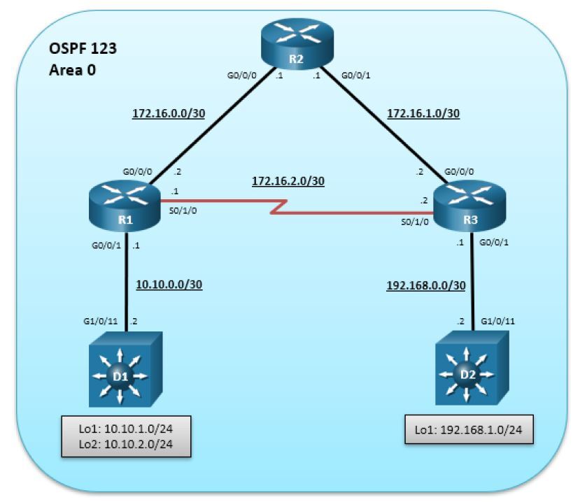
Imagen Topologia
Sobre
Creacion laboratorio IOU WEB Desde 0
NETMAP
1:0/0 2:0/0
1:0/1 4:0/1
1:1/0 3:1/0
2:0/1 3:0/0
3:0/1 5:0/1
Dispositivos
| ID | Name | IOS | Eth | Ser | Picture |
|---|---|---|---|---|---|
| 1 | R1 | L3 15.4.1T A | 1 | 1 | Router |
| 2 | R2 | L3 15.4.1T A | 1 | 1 | Router |
| 3 | R3 | L3 15.4.1T A | 1 | 1 | Router |
| 4 | D1 | L2 15.2D | 1 | 0 | L3 Switch |
| 5 | D2 | L2 15.2D | 1 | 0 | L3 Switch |
Tabla Direccionamiento
| Dispositivo | Interfaz | IPv4 Address | Subnet |
|---|---|---|---|
| D1 | G0/0/1 | 10.10.0.2 | 255.255.255.252 |
| L1 | 10.10.1.1 | 255.255.255.0 | |
| L2 | 10.10.2.1 | 255.255.255.0 | |
| R1 | G0/0/0 | 172.16.0.2 | 255.255.255.252 |
| G0/0/1 | 10.10.0.1 | 255.255.255.252 | |
| S0/1/0 | 172.16.2.1 | 255.255.255.252 | |
| R2 | G0/0/0 | 172.16.0.1 | 255.255.255.252 |
| G0/0/1 | 172.16.1.1 | 255.255.255.252 | |
| R3 | G0/0/0 | 172.16.1.2 | 255.255.255.252 |
| G0/0/1 | 192.168.0.1 | 255.255.255.252 | |
| S0/1/0 | 172.16.2.2 | 255.255.255.252 | |
| D2 | G0/0/1 | 192.168.0.2 | 255.255.255.252 |
| L1 | 192.168.1.1 | 255.255.255.0 |
Configuracion Parte 1
Configuracion Basica, hostname e IP
R1
hostname R1
no ip domain lookup
line con 0
logging sync
exec-time 0 0
exit
banner motd # This is R1, Path Control Using PBR #
interface G0/0/0
description Connection to R2
ip add 172.16.0.2 255.255.255.252
no shut
exit
interface S0/1/0
description Serial Connection to R3
ip add 172.16.2.1 255.255.255.252
no shut
exit
interface G0/0/1
description Connection to D1
ip add 10.10.0.1 255.255.255.252
no shut
exit
R2
hostname R2
no ip domain lookup
line con 0
logging sync
exec-time 0 0
exit
banner motd # This is R2, Path Control Using PBR #
interface G0/0/0
description Connection to R1
ip add 172.16.0.1 255.255.255.252
no shut
exit
interface GigabitEthernet0/0/1
description Connection to R3
ip address 172.16.1.1 255.255.255.252
no shut
exit
R3
hostname R3
no ip domain lookup
line con 0
logging sync
exec-time 0 0
exit
banner motd # This is R3, Path Control Using PBR #
interface G0/0/0
description Connection to R2
ip add 172.16.1.2 255.255.255.252
no shut
exit
interface S0/1/0
description Serial Connection to R1
ip add 172.16.2.2 255.255.255.252
no shut
exit
interface G0/0/1
description Connection to D2
ip add 192.168.0.1 255.255.255.252
no shut
exit
Switch D1
hostname D1
no ip domain lookup
line con 0
exec-timeout 0 0
logging synchronous
exit
banner motd # This is D1, Path Control Using PBR #
interface G1/0/11
no switchport
description Connects to R1
ip address 10.10.0.2 255.255.255.252
no shut
exit
interface Loopback 1
description Interface simulates network
ip ospf network point-to-point
ip address 10.10.1.1 255.255.255.0
exit
interface Loopback 2
description Interface simulates network
ip ospf network point-to-point
ip address 10.10.2.1 255.255.255.0
exit
Switch D2
hostname D2
no ip domain lookup
line con 0
logging sync
exec-time 0 0
exit
banner motd # This is D2, Path Control Using PBR #
interface G1/0/11
no switchport
description Connects to R3
ip address 192.168.0.2 255.255.255.252
no shut
exit
interface Loopback 1
description Interface simulates network
ip ospf network point-to-point
ip address 192.168.1.1 255.255.255.0
exit
Configuracion Parte 2
Implementacion de OSPF
D1
ip routing
router ospf 123
router-id 1.1.1.2
auto-cost reference-bandwidth 1000
network 10.10.0.0 0.0.0.3 area 0
network 10.10.1.0 0.0.0.255 area 0
network 10.10.2.0 0.0.0.255 area 0
R1
router ospf 123
router-id 1.1.1.1
auto-cost reference-bandwidth 1000
network 10.10.0.0 0.0.0.3 area 0
network 172.16.0.0 0.0.0.3 area 0
network 172.16.2.0 0.0.0.3 area 0
R2
router ospf 123
router-id 2.2.2.1
auto-cost reference-bandwidth 1000
network 172.16.0.0 0.0.0.3 area 0
network 172.16.1.0 0.0.0.3 area 0
R3
router ospf 123
router-id 3.3.3.1
auto-cost reference-bandwidth 1000
network 192.168.0.0 0.0.0.3 area 0
network 172.16.1.0 0.0.0.3 area 0
network 172.16.2.0 0.0.0.3 area 0
D2
ip routing
router ospf 123
router-id 3.3.3.2
auto-cost reference-bandwidth 1000
network 192.168.0.0 0.0.0.3 area 0
network 192.168.1.0 0.0.0.255 area 0
Verificar Funcionamiento Parte 2
D1
show ip route ospf | begin Gateway
D2
show ip route ospf | begin Gateway
R1
show ip route ospf | begin Gateway
R2
show ip route ospf | begin Gateway
R3
show ip route ospf | begin Gateway
TCLSH
tclsh
foreach address {
10.10.0.1
10.10.0.2
10.10.1.1
10.10.2.1
172.16.0.1
172.16.0.2
172.16.1.1
172.16.1.2
172.16.2.1
172.16.2.2
192.168.0.1
192.168.0.2
192.168.1.1
} { ping $address repeat 5 size 1500 }
Ping D1 a D2 via loopback
ping 192.168.1.1 source 10.10.1.1
Traceroute D1 a D2 via loopback
traceroute 192.168.1.1 source 10.10.1.1
Configuracion Parte 3
Usar PBR a travez de Route-Map con ACL
R1
!# Crear ACL
ip access-list standard Lo2-ACL
remark ACL matches D1 Lo2 traffic
permit 10.10.2.0 0.0.0.255
exit
!# Crear Route-MAP
route-map R1-to-R3 permit
description RM to forward Lo2 traffic to R3
match ip address Lo2-ACL
set ip next-hop 172.16.2.2
exit
!# Aplicar PBR
interface g0/0/1
ip policy route-map R1-to-R3
end
Visualizar R1
show route-map
show ip policy
Configuracion Parte 4
PBR Local
R1
!# Crear ACL
ip access-list extended R1-TRAFFIC
permit ip any 192.168.1.0 0.0.0.255
exit
!# Crear Route-Map
route-map LOCAL-PBR permit
match ip address R1-TRAFFIC
set ip next-hop 172.16.2.2
exit
!# Aplicar PBR Local
ip local policy route-map LOCAL-PBR
exit
Visualizar R1
traceroute 192.168.1.1
traceroute 192.168.0.2
show route-map