Info
ERRATA: La Ipv6 las da el profe, se usan pero no se calculan
Actividad:
Onedrive Nuevo | Onedrive Terminado
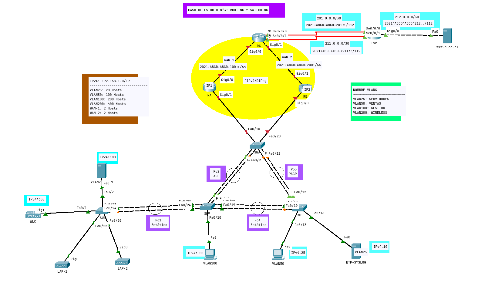
Imagen Topologia
Apoyo:
Requerimientos
A. IMPLEMENTACIÓN DIRECCIONAMIENTO IPv4/IPv6:
- Calcular VLSM a partir de la dirección de red 192.168.1.0/19. Asignar IPv4 a equipos finales e interfaces de equipos de conmutación correspondiente.
- Asignar IPv6 en porción de red correspondiente.
- La conexión externa ya tiene direccionamiento IPv4/IPv6 asignado.
B. IMPLEMENTACIÓN DE TECNOLOGÍAS DE CAPA 2:
- Crear las VLANs propuesta en todos los switches.
- Asignar las interfaces correspondientes a la VLAN de Datos. Para la porción inalámbrica, tanto servidor DHCP, WLC y LAP deben pertenecer a la VLAN 200.
- Implementar solución de agregado de enlaces en capa 2, utilizando protocolos de encapsulación propuestos. Considerar al SWA como equipo que negocia y el otro extremo escucha según protocolo de encapsulamiento propuestos.
- Permitir por los Port-Channels creados, solo el paso de VLANs correspondientes.
- Desactivar protocolo DTP en Port-Channels creados.
- Implementar PVST+ Rápido en todos los equipos de conmutación de la red.
- En interfaces de acceso deberá implementar mecanismos de estabilización de STP correspondiente. Este requerimiento no aplica para el switch SWD.
- En el SWB en las puertas de acceso implementar seguridad de puerto dinámica.
- En el SWC en las puertas de acceso, implementar seguridad de puerto con aprendizaje con un máximo de 3 direcciones MAC, y en caso de exceder deberá generar envío de mensaje SYSLOG.
C. IMPLEMENTACIÓN DE TECNOLOGÍAS DE CAPA 3:
- En RA y RB deberá realizar el enrutamiento intervlan, utilizando la IP propuesta, el número de subinterfaz y la encapsulación será acorde al número de VLAN.
- En RA y RB deberá implementar HSRP, donde la VLAN25 y VLAN50 deberá preferir RA y la VLAN100 y VLAN200 deberá preferir RB. Las interfaces que queden como activo deberá utilizar una prioridad de 120 y la de respaldo de 90. La IP virtual será la última asignable de cada segmento de red. No olvide asegurar los roles con comando apropiado.
- Habilitar protocolo RIPv2, donde debe desactivar la sumarización automática, además de enrutar las redes directamente conectadas. No olvide configurar interfaces pasivas.
- Habilitar protocolo RIPng, con el proceso llamado CASO3. Habilitar las interfaces correspondientes.
- Entre router RC e ISP deberá implementar ruta por defecto flotante. Considerar tanto para IPv4/IPv6 el enlace serial 0/0/1 como respaldo, utilizando un AD de 100. Esta configuración debe realizarla de ida y vuelta.
- Redistribuir ruta por defecto flotante en RIPv2 y RIPng.
D. IMPLEMENTACIÓN DE SOLUCIONES INALÁMBRICAS:
- Configurar WLC, utilizando la IP de administración según es señalado, para el segmento de red calculado. Por otro lado, la administración y la otorgación de IP a los AP ligeros (LAP) será a través del servidor DHCP. Que deberá proporcionar IP limitando a un máximo de 20 IP que serán entregadas.
- Crear una cuenta de administración con el nombre de CASO3 y password Cisco123+
- En el asistente le solicitará crear una red inalámbrica, la cual deberá llamarse Corporativa y la clave pre-compartida (WPA2-PSK) que debe utilizar será Duoc123+. No utilizará VLAN de Administración.
- Deberá luego ingresar nuevamente a página de administración del WLC, donde deberá crear una red llamada Invitados, y una clave pre-compartida con la credencial de Duoc123+
- Crear un grupo de AP llamado Corporativa donde deberá asociar el SSID Corporativa y el AP Ligero LAP-2.
- Crear un grupo de AP llamado Invitados donde deberá asociar el SSID Invitados y el AP Ligero LAP-1.
- Asociar el Smartphone - Invitados a la red inalámbrica Invitados y el Smartphone - Corporativa a la red inalámbrica Corporativa.
- Comprobar que WLC entregue información a LAP mediante protocolo CAPWAP.
- Comprobar conectividad completa en la topología.
E. COMPROBACIÓN DE SERVICIOS Y CONECTIVIDAD:
- Habilitar servicio NTP, donde los routers RA, RB y RC se sincronicen en tiempo y hora con servidor NTP que está en VLAN25.
- En los routers RA, RB y RC habilitar el servicio Syslog en donde todos los eventos generados serán enviados al servidor SYSLOG que está en la VLAN25.
- Configurar servicio DNS para que traduzca el sitio de www.duoc.cl a nivel de IPv4/IPv6.
- Comprobar conectividad completa en la topología.
Calculo VLSM
RED: 192.168.1.0/19
| Nombre | Host | Adress | Mask | Mask Decimal | Rango Asignable |
|---|---|---|---|---|---|
| Vlan 200 | 400 | 192.168.0.0 | /23 | 255.255.254.0 | 192.168.0.1 - 192.168.1.254 |
| Vlan 100 | 200 | 192.168.2.0 | /24 | 255.255.255.0 | 192.168.2.1 - 192.168.2.254 |
| Vlan 50 | 100 | 192.168.3.0 | /25 | 255.255.255.128 | 192.168.3.1 - 192.168.3.126 |
| Vlan 25 | 20 | 192.168.3.128 | /27 | 255.255.255.224 | 192.168.3.129 - 192.168.3.158 |
| Wan 1 | 2 | 192.168.3.160 | /30 | 255.255.255.252 | 192.168.3.161 - 192.168.3.162 |
| Wan 2 | 2 | 192.168.3.164 | /30 | 255.255.255.252 | 192.168.3.165 - 192.168.3.166 |
Equipos finales
duoc.cl
- IPv4: 212.0.0.2
- SubNet: 255.255.255.252
- Default Gateway: 212.0.0.1
- DNS: 212.0.0.2
- IPV6: 2020:ABCD:ABCD:212::2 /112
- Link Local: FE80::209:7CFF:FE7C:3823
- DGv6: 2020:ABCD:ABCD:212::1
- DNSv6: 2020:ABCD:ABCD:212::2
Server NTP-SYSLOG
- IPv4: 192.168.3.138
- Subnet: 255.255.255.224
- DGv4: 192.168.3.158
- DNS: 212.0.0.2
Vlan 50
- IPv4: 192.168.3.25
- Subnet: 255.255.255.128
- DGv4: 192.168.3.126
- DNS: 212.0.0.2
Vlan 100
- IPv4: 192.168.2.50
- Subnet: 255.255.255.0
- DGv4: 192.168.2.254
- DNS: 212.0.0.2
Server Vlan 200
- IPv4: 192.168.0.100
- Subnet: 255.255.254.0
- DGv4: 192.168.1.254
- DNS: 212.0.0.2
WLC (300) (1.44)
- IPv4: 192.168.1.44
- Subnet: 255.255.255.0
- DGv4: 192.168.1.254
- DNS: 212.0.0.2
SWD
hostname SWD
!
vlan 25
name SERVIDORES
exit
!
vlan 50
name VENTAS
exit
!
vlan 100
name GESTION
exit
!
vlan 200
name WIRELESS
exit
!
int range f0/1-2
switchport mode access
switchport access vlan 200
exit
!
int range f0/20,fa0/22
switchport mode access
switchport access vlan 200
exit
!
interface range fa0/23-24
channel-group 1 mode on
no shut
exit
!
interface Port-channel 1
switchport mode trunk
switchport trunk allowed vlan 25,50,100,200
switchport nonegotiate
no shut
exit
!
spanning-tree mode rapid-pvst
SWB
hostname SWB
!
vlan 25
name SERVIDORES
exit
!
vlan 50
name VENTAS
exit
!
vlan 100
name GESTION
exit
!
vlan 200
name WIRELESS
exit
!
int F0/10
switchport mode access
switchport access vlan 100
spanning-tree bpduguard enable
spanning-tree portfast
switchport port-security
exit
!
interface range fa0/23-24
channel-group 1 mode on
no shut
exit
!
interface range fa0/18-19
channel-group 4 mode on
no shut
exit
!
interface range fa0/8-9
channel-group 2 mode passive
no shut
exit
!
interface Port-channel 1
switchport mode trunk
switchport trunk allowed vlan 25,50,100,200
switchport nonegotiate
no shut
exit
!
interface Port-channel 2
switchport mode trunk
switchport trunk allowed vlan 25,50,100,200
switchport nonegotiate
no shut
exit
!
interface Port-channel 4
switchport mode trunk
switchport trunk allowed vlan 25,50,100,200
switchport nonegotiate
no shut
exit
!
spanning-tree mode rapid-pvst
SWC
hostname SWC
!
vlan 25
name SERVIDORES
exit
!
vlan 50
name VENTAS
exit
!
vlan 100
name GESTION
exit
!
vlan 200
name WIRELESS
exit
!
int F0/13
switchport mode access
switchport access vlan 50
spanning-tree bpduguard enable
spanning-tree portfast
switchport port-security
switchport port-security maximum 3
switchport port-security mac-address sticky
switchport port-security violation protect
exit
!
int F0/16
switchport mode access
switchport access vlan 25
spanning-tree bpduguard enable
spanning-tree portfast
switchport port-security
switchport port-security maximum 3
switchport port-security mac-address sticky
switchport port-security violation protect
exit
!
interface range fa0/11-12
channel-group 3 mode auto
no shut
exit
!
interface range fa0/18-19
channel-group 4 mode on
no shut
exit
!
interface Port-channel 3
switchport mode trunk
switchport trunk allowed vlan 25,50,100,200
switchport nonegotiate
no shut
exit
!
interface Port-channel 4
switchport mode trunk
switchport trunk allowed vlan 25,50,100,200
switchport nonegotiate
no shut
exit
!
spanning-tree mode rapid-pvst
SWA
hostname SWA
!
vlan 25
name SERVIDORES
exit
!
vlan 50
name VENTAS
exit
!
vlan 100
name GESTION
exit
!
vlan 200
name WIRELESS
exit
!
int F0/10
switchport mode trunk
switchport trunk allowed vlan 25,50,100,200
switchport nonegotiate
no shut
exit
!
int F0/20
switchport mode trunk
switchport trunk allowed vlan 25,50,100,200
switchport nonegotiate
no shut
exit
!
interface range fa0/11-12
channel-group 3 mode desirable
no shut
exit
!
interface range fa0/8-9
channel-group 2 mode active
no shut
exit
!
interface Port-channel 3
switchport mode trunk
switchport trunk allowed vlan 25,50,100,200
switchport nonegotiate
no shut
exit
!
interface Port-channel 2
switchport mode trunk
switchport trunk allowed vlan 25,50,100,200
switchport nonegotiate
no shut
exit
!
spanning-tree mode rapid-pvst
RA
HOSTNAME RA
!
ipv6 unicast-routing
!
IPV6 ROUTER RIP CASO3
exit
!
int g0/0
ip add 192.168.3.161 255.255.255.252
ipv6 add 2021:ABCD:ABCD:100::1/64
ipv6 rip CASO3 enable
no shut
exit
!
int g0/1
no shut
exit
!
INT G0/1.25
Encapsulation dot1q 25
ip address 192.168.3.129 255.255.255.224
standby version 2
standby 25 ip 192.168.3.158
standby 25 priority 120
standby 25 preempt
ipv6 rip CASO3 enable
EXIT
!
INT G0/1.50
encapsulation dot1Q 50
ip address 192.168.3.1 255.255.255.128
standby version 2
standby 50 ip 192.168.3.126
standby 50 priority 120
standby 50 preempt
ipv6 rip CASO3 enable
EXIT
!
INT GI0/1.100
encapsulation dot1Q 100
ip address 192.168.2.1 255.255.255.0
standby version 2
standby 100 ip 192.168.2.254
standby 100 priority 90
standby 100 preempt
ipv6 rip CASO3 enable
EXIT
!
INT GI0/1.200
encapsulation dot1Q 200
ip address 192.168.0.1 255.255.254.0
standby version 2
standby 200 ip 192.168.1.254
standby 200 priority 90
standby 200 preempt
ipv6 rip CASO3 enable
EXIT
!
router rip
version 2
no auto-summary
passive-interface g0/2
passive-interface GigabitEthernet0/1.25
passive-interface GigabitEthernet0/1.50
passive-interface GigabitEthernet0/1.100
passive-interface GigabitEthernet0/1.200
network 192.168.0.0
network 192.168.2.0
network 192.168.3.0
network 192.168.3.128
network 192.168.3.160
exit
!
ntp server 192.168.3.138
!
logging trap debugging
logging 192.168.3.138
!
RB
HOSTNAME RB
!
ipv6 unicast-routing
!
IPV6 ROUTER RIP CASO3
exit
!
int g0/1
ip add 192.168.3.166 255.255.255.252
ipv6 add 2021:ABCD:ABCD:200:2/64
ipv6 rip CASO3 enable
no shut
exit
!
int g0/0
no shut
exit
!
INT G0/0.25
Encapsulation dot1q 25
ip address 192.168.3.130 255.255.255.224
standby version 2
standby 25 ip 192.168.3.158
standby 25 priority 90
standby 25 preempt
ipv6 rip CASO3 enable
EXIT
!
INT G0/0.50
encapsulation dot1Q 50
ip address 192.168.3.2 255.255.255.128
standby version 2
standby 50 ip 192.168.3.126
standby 50 priority 90
standby 50 preempt
ipv6 rip CASO3 enable
EXIT
!
INT GI0/0.100
encapsulation dot1Q 100
ip address 192.168.2.2 255.255.255.0
standby version 2
standby 100 ip 192.168.2.254
standby 100 priority 120
standby 100 preempt
ipv6 rip CASO3 enable
EXIT
!
INT GI0/0.200
encapsulation dot1Q 200
ip address 192.168.0.2 255.255.254.0
standby version 2
standby 200 ip 192.168.1.254
standby 200 priority 120
standby 200 preempt
ipv6 rip CASO3 enable
EXIT
!
router rip
version 2
no auto-summary
passive-interface g0/2
no passive-interface GigabitEthernet0/1.25
no passive-interface GigabitEthernet0/1.50
no passive-interface GigabitEthernet0/1.100
no passive-interface GigabitEthernet0/1.200
passive-interface GigabitEthernet0/0.25
passive-interface GigabitEthernet0/0.50
passive-interface GigabitEthernet0/0.100
passive-interface GigabitEthernet0/0.200
network 192.168.0.0
network 192.168.2.0
network 192.168.3.0
network 192.168.3.128
network 192.168.3.164
exit
!
ntp server 192.168.3.138
!
logging trap debugging
logging 192.168.3.138
!
RC
HOSTNAME RC
!
ipv6 unicast-routing
!
int g0/0
ip add 192.168.3.162 255.255.255.252
ipv6 add 2021:ABCD:ABCD:100::2/64
ipv6 rip CASO3 enable
no shut
exit
!
int g0/1
ip add 192.168.3.165 255.255.255.252
ipv6 add 2021:ABCD:ABCD:200::1/64
ipv6 rip CASO3 enable
no shut
exit
!
ip route 0.0.0.0 0.0.0.0 201.0.0.2
ip route 0.0.0.0 0.0.0.0 211.0.0.2 100
!
IPV6 ROUTE ::/0 2021:ABCD:ABCD:201::2
IPV6 ROUTE ::/0 2021:ABCD:ABCD:211::2 100
!
router rip
version 2
no auto-summary
network 192.168.3.164
network 192.168.3.160
default-information originate
exit
!
IPV6 ROUTER RIP CASO3
redistribute static
exit
!
ntp server 192.168.3.138
!
logging trap debugging
logging 192.168.3.138
!
ISP
hostname ISP
!
ipv6 unicast-routing
!
ip route 0.0.0.0 0.0.0.0 201.0.0.1
ip route 0.0.0.0 0.0.0.0 211.0.0.1 100
!
IPV6 ROUTE ::/0 2021:ABCD:ABCD:201::1
IPV6 ROUTE ::/0 2021:ABCD:ABCD:211::1 100
!
Extra
Comandos de apoyo en Router
HOSTNAME RX
!
ipv6 unicast-routing
!
INT G0/A.A
Encapsulation dot1q
ip address aaaa aaaa
standby version aaa
standby aa ip aaaa
standby aa priority aaa
standby aa preempt
EXIT
!
router rip
version 2
passive-interface g0/2
no auto-summary
network AAAA
default-information originate
exit
!
int g0/A
ipv6 rip AAAA enable
no shut
exit
!
IPV6 ROUTER RIP AAAA
redistribute static
exit
!
!
ip route 0.0.0.0 0.0.0.0 aaaaa
!
IPV6 ROUTE ::/0 aaaaaa
!
ntp server XXXX