Info
ATENCION
Este Examen tiene 2 Formas, A o B, Son los mismos dispositivos pero cambian las configuraciones levemente, por ejemplos, IP de enlaces y numeros de VLAN
Importante
Estos comandos son de la forma A
1.- Direccionamiento
Considere la siguiente información para el direccionamiento de cada uno de los equipos e interfaces.
Tabla Direcciones
| RED | NOMBRE | IP |
|---|---|---|
| VLAN 10 | VENTAS | 172.16.10.0/24 |
| VLAN 20 | ADMINISTRATIVOS | 172.16.20.0/24 |
| VLAN 30 | GERENCIA | 172.16.30.0/24 |
| VLAN 40 | ENLACE_WIRELESS | 172.16.40.0/24 |
| VLAN 99 | NATIVA/ADMIN | 10.11.12.0/26 |
| RED DNS | DNS | 200.0.2.0/30 |
| RED HTTP/HTTPS | HTTP/HTTPS | 199.9.9.0/30 |
| ENLACE_1 | ENLACE_1 | 10.0.1.0/30 |
| ENLACE_2 | ENLACE_2 | 10.0.2.0/30 |
| RED WIRELESS | AP_VISITAS | 192.168.100.0/24 |
2.- Configuracion Etherchannel
Se le solicita implementar 5 enlaces Etherchannel según indica la topología, adicionalmente para cada enlace los dispositivos (MLS1 y MLS2) se deben configurar para que negocien el protocolo a utilizar y los dispositivos (SW1, SW2, SW3) deben estar a la escucha para establecer conexión, según las siguientes instrucciones.
Tabla Etherchannel
| Conexion | Tipo | Port-channel |
|---|---|---|
| MLS1 a SW1 | PAGP | Po2 |
| MLS1 a SW2 | LACP | Po4 |
| MLS2 a SW2 | LACP | Po5 |
| MLS2 a SW3 | PAGP | Po3 |
| MLS1 a MLS2 | STATIC | Po1 |
3.- Configuracion Spanning-tree
Para evitar la sobrecarga de un equipo para el manejo del trafico de todas las VLAN, se debe configurar el protocolo STP, dejando a:
- MLS1 como root bridge para VLAN10 y VLAN30, secundaria VLAN20 y VLAN40.
- MLS2 debe ser configurado como root bridge de VLAN20 y VLAN40, secundaria VLAN10 y VLAN30. Para los puertos de acceso se debe configurar portfast y aplicar algún tipo de seguridad que permita mantener la integridad de las configuraciones evitando que los puertos de acceso puedan enviar y recibir BPDU.
4.- Configuracion Servicio DHCP
Configure en la capa de distribución (MLS1 y MLS2) el servicio DHCP para las VLAN 10, 20, 30 y 40, debe respetar el formato del nombre, por ejemplo:VLANXX donde XX corresponde al número de la VLAN. Considere entregar desde la IP .80 a la .120 y el DNS corresponde al equipo de la red ISP (200.0.2.2). Recuerde la condición de redundancia de ambos equipos.
5.- Configuracion Equipos Capa De Acceso Y Seguridad L2
Para los equipos SW1, SW2 y SW3, crear las VLAN indicadas y asignar en cada uno de ellos los puertos de acuerdo a la siguiente tabla
Tabla Asignación de puertos y VLAN capa de Acceso
Nota: Esta configuracion se hace en los 3 switch
| VLAN | Puerto |
|---|---|
| 10 | Fa0/5-Fa0/13 |
| 20 | Fa0/14-0/19 |
| 30 | Fa0/20-Fa0/23 |
| 40 | G0/1 |
| Por motivos de seguridad, se solicita activar los siguientes parámetros: | |
SW1 y SW2 |
- Activar seguridad de puerto
- Permitir el aprendizaje persistente de un máximo de 1 direcciones MAC
En caso de violación de seguridad, dejar las interfaces bloqueadas en estado ERRDISABLE.
SW3
- Activar seguridad de puerto
- Permitir el aprendizaje de un máximo de 1 dirección MAC segura
- Los puertos usados deben aprender la MAC de manera estática
- Los puertos no usados de cada VLAN deberán aprender la MAC de manera persistente.
Apagar todos los puertos que no serán usados y deshabilitar la negociación automática. En los enlaces troncales solo se debe habilitar el paso de las VLAN10, VLAN20, VLAN30, VLAN40. Para el trafico no etiquetado se debe usar VLAN99.
6.- Configuracion HSRP
Se debe montar una estructura redundante entre MLS1 y MLS2 para todas las redes VLAN. Siga el siguiente direccionamiento. Considere que el equipo Activo para VLAN10 y VLAN30 deberá ser el MLS1 (usar una prioridad de 150) y MLS2 debe estar activo para VLAN20 y VLAN40. En caso que se produzca una falla en el equipo, tome su lugar el dispositivo que está en standby. Cuando el equipo retome su normal funcionamiento, deberá recuperar su condición de equipo activo. Según información de la EMPRSA, la red presenta un problema de conectividad cada cierto tiempo en uno de sus enlaces, pero el protocolo de redundancia implementado no funciona completamente bien, según reportes MLS1 y MLS2 cada cierto tiempo pierde conectividad a internet, pero para las VLAN sigue manteniendo su rol de activo al igual que MLS2. Se solicita poder solucionar este problema mediante la configuración de un sistema de monitoreo en el protocolo.
| RED | DLS1 | DLS2 | GATEWAY |
|---|---|---|---|
| VLAN 10 | 172.16.10.1 | 172.16.10.2 | 172.16.10.254 |
| VLAN 20 | 172.16.20.1 | 172.16.20.2 | 172.16.20.254 |
| VLAN 30 | 172.16.30.1 | 172.16.30.2 | 172.16.30.254 |
| VLAN 40 | 172.16.40.1 | 172.16.40.2 | 172.16.40.254 |
7.- Acceso Remoto
Configure acceso remoto usando SSH en los equipos de red de la Capa de Acceso. Considere los siguientes parámetros:
- Contraseña secreta: ary3112
- Nombre de Dominio: ary.duoc.cl
- Longitud RSA: 1024 bits
- Usuario/Pass (MD5): admin/cisco123
- Acceso usando la autenticación local
8.- Red Wireless
Configurar la red WIFI considerando los siguientes parámetros
| 2.4Ghz | 5Ghz | |
|---|---|---|
| SSID | VISITAS | VISITAS 5G |
| Canal | 6 | automatico |
| Contraseña | ary.3112 | ary.3112 |
| Encriptacion | RSA | RSA |
| En servicio DHCP del router AP_VISITAS, el direccionamiento debe comenzar desde la IP .80 con una cantidad máxima de 40 usuarios. |
9.- Enrutamiento
En MLS1 y MLS2 se deben configurar rutas estáticas hacia rutas en INTERNET con IP del próximo salto, La nube INTERNET ya se encuentra configurada, por lo cual debe verificar conectividad, para esto debe realizar un ping desde cada VLAN y corroborar salida a internet. Rutas a configurar desde MLS1 y MLS2 Ruta hacia servidor DNS, servidor HTTP/HTTPS, y salida a internet 8.8.8.8.
10.- Resolucion De Problemas De Conectividad
Se ha detectado una falla a nivel de enrutamiento, ya que se han realizado pruebas de conectividad y desde ninguna VLAN tienen salida a internet y no pueden llegar a la IP 8.8.8.8. Se solicita poder revisar las configuraciones del router ISP1 que está conectado a MLS1 y MLS2, para lograr la salida a internet. Se recomienda revisar las rutas estáticas desde ISP1 hacia las VLAN. Para poder revisar las configuraciones de ISP1, se debe conectar mediante SSH desde MLS1 con los siguientes parámetros de conexión:
- Usuario: admin.isp2
- Password: isp2.acceso
- IP: 10.0.1.2
- Password Modo Privilegiado: cisco123
Comando:
ssh -l usuario 10.0.1.2
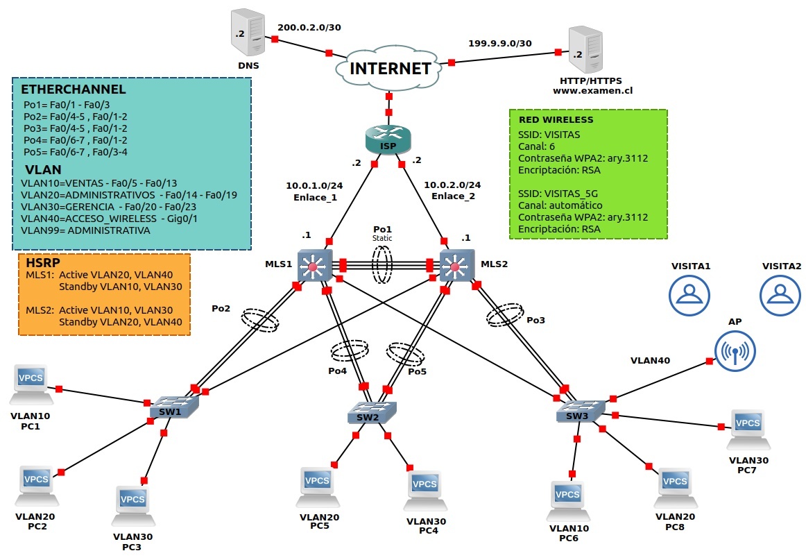
Topologias
Forma A
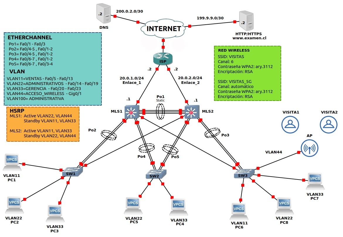
Forma B
Descargar
Configuracion
SW1
hostname SW1
!
vlan 10
name VENTAS
exit
!
vlan 20
name ADMINISTRATIVOS
exit
!
vlan 30
name GERENCIA
exit
!
vlan 40
name ENLACE_WIRELESS
exit
!
vlan 99
name NATIVA/ADMIN
exit
!
interface range fa0/1-2
channel-group 2 mode auto
no shut
exit
!
interface Port-channel 2
switchport mode trunk
switchport trunk allowed vlan 10,20,30,40,99
switchport nonegotiate
no shut
exit
!
int range fa0/5-13
switchport mode access
switchport access vlan 10
switchport port-security
switchport port-security maximum 1
switchport port-security mac-address sticky
switchport port-security violation shutdown
spanning-tree portfast
spanning-tree bpduguard enable
exit
!
int range fa0/14-19
switchport mode access
switchport access vlan 20
switchport port-security
switchport port-security maximum 1
switchport port-security mac-address sticky
switchport port-security violation shutdown
spanning-tree portfast
spanning-tree bpduguard enable
exit
!
int range fa0/20-23
switchport mode access
switchport access vlan 30
switchport port-security
switchport port-security maximum 1
switchport port-security mac-address sticky
switchport port-security violation shutdown
spanning-tree portfast
spanning-tree bpduguard enable
exit
!
int range fa0/3,fa0/4,fa0/6-14,fa0/16-20,fa0/22-23
shut
exit
!
user admin PASS cisco123
ip domain-name ary.duoc.cl
crypto key generate rsa
line vty 0 4
login local
exit
!
SW2
hostname SW2
!
vlan 10
name VENTAS
exit
!
vlan 20
name ADMINISTRATIVOS
exit
!
vlan 30
name GERENCIA
exit
!
vlan 40
name ENLACE_WIRELESS
exit
!
vlan 99
name NATIVA/ADMIN
exit
!
interface range fa0/1-2
channel-group 4 mode pasive
no shut
exit
!
interface Port-channel 4
switchport mode trunk
switchport trunk allowed vlan 10,20,30,40,99
switchport nonegotiate
no shut
exit
!
interface range fa0/3-4
channel-group 5 mode pasive
no shut
exit
!
interface Port-channel 5
switchport mode trunk
switchport trunk allowed vlan 10,20,30,40,99
switchport nonegotiate
no shut
exit
!
int range fa0/5-13
switchport mode access
switchport access vlan 10
switchport port-security
switchport port-security maximum 1
switchport port-security mac-address sticky
switchport port-security violation shutdown
spanning-tree portfast
spanning-tree bpduguard enable
exit
!
int range fa0/14-19
switchport mode access
switchport access vlan 20
switchport port-security
switchport port-security maximum 1
switchport port-security mac-address sticky
switchport port-security violation shutdown
spanning-tree portfast
spanning-tree bpduguard enable
exit
!
int range fa0/20-23
switchport mode access
switchport access vlan 30
switchport port-security
switchport port-security maximum 1
switchport port-security mac-address sticky
switchport port-security violation shutdown
spanning-tree portfast
spanning-tree bpduguard enable
exit
!
int range fa0/5-6,fa0/8-18,fa0/20-24
shut
exit
!
user admin PASS cisco123
ip domain-name ary.duoc.cl
crypto key generate rsa
1024
line vty 0 4
login local
exit
!
SW3
hostname SW3
!
vlan 10
name VENTAS
exit
!
vlan 20
name ADMINISTRATIVOS
exit
!
vlan 30
name GERENCIA
exit
!
vlan 40
name ENLACE_WIRELESS
exit
!
vlan 99
name NATIVA/ADMIN
exit
!
interface range fa0/1-2
channel-group 3 mode auto
no shut
exit
!
interface Port-channel 3
switchport mode trunk
switchport trunk allowed vlan 10,20,30,40,99
switchport nonegotiate
no shut
exit
!
int range fa0/5-13
switchport mode access
switchport access vlan 10
switchport port-security
switchport port-security maximum 1
switchport port-security mac-address sticky
switchport port-security violation shutdown
spanning-tree portfast
spanning-tree bpduguard enable
exit
!
int range fa0/14-19
switchport mode access
switchport access vlan 20
switchport port-security
switchport port-security maximum 1
switchport port-security mac-address sticky
switchport port-security violation shutdown
spanning-tree portfast
spanning-tree bpduguard enable
exit
!
int range fa0/20-23
switchport mode access
switchport access vlan 30
switchport port-security
switchport port-security maximum 1
switchport port-security mac-address sticky
switchport port-security violation shutdown
spanning-tree portfast
spanning-tree bpduguard enable
exit
!
int range g0/1
switchport mode access
switchport access vlan 40
switchport port-security
switchport port-security maximum 1
switchport port-security mac-address sticky
switchport port-security violation shutdown
spanning-tree portfast
spanning-tree bpduguard enable
exit
!
user admin PASS cisco123
ip domain-name ary.duoc.cl
crypto key generate rsa
1024
line vty 0 4
login local
exit
!
MSL1
hostname MSL1
!
vlan 10
name VENTAS
exit
!
vlan 20
name ADMINISTRATIVOS
exit
!
vlan 30
name GERENCIA
exit
!
vlan 40
name ENLACE_WIRELESS
exit
!
vlan 99
name NATIVA/ADMIN
exit
!
ip route 10.0.1.1 255.255.255.0 10.0.1.2
!
interface g0/1
no switchport
ip address 10.0.1.1 255.255.255.0
no shut
EXIT
!
ip dhcp excluded-address 172.16.10.1 172.16.10.79
ip dhcp excluded-address 172.16.20.1 172.16.20.79
ip dhcp excluded-address 172.16.30.1 172.16.30.79
ip dhcp excluded-address 172.16.40.1 172.16.40.79
!
ip dhcp pool VLAN10
network 172.16.10.1 255.255.255.0
default-router 172.16.10.254
dns-server 200.0.2.2
exit
!
ip dhcp pool VLAN20
network 172.16.20.1 255.255.255.0
default-router 172.16.20.254
dns-server 200.0.2.2
exit
!
ip dhcp pool VLAN30
network 172.16.30.1 255.255.255.0
default-router 172.16.30.254
dns-server 200.0.2.2
exit
!
ip dhcp pool VLAN40
network 172.16.40.1 255.255.255.0
default-router 172.168.40.254
dns-server 200.0.2.2
exit
!
INT VLAN 10
ip address 172.16.10.1 255.255.255.0
standby version 2
standby 10 ip 172.16.10.254
standby 10 priority 150
standby 10 preempt
EXIT
!
INT VLAN 20
ip address 172.16.20.1 255.255.255.0
standby version 2
standby 20 ip 172.16.20.254
standby 20 priority 120
standby 20 preempt
EXIT
!
INT VLAN 30
ip address 172.16.30.1 255.255.255.0
standby version 2
standby 30 ip 172.16.30.254
standby 30 priority 150
standby 30 preempt
EXIT
!
INT VLAN 40
ip address 172.16.40.1 255.255.255.0
standby version 2
standby 40 ip 172.168.40.254
standby 40 priority 120
standby 40 preempt
EXIT
!
interface range fa0/1-3
channel-group 1 mode on
no shut
exit
!
interface Port-channel 1
switchport mode trunk
switchport trunk allowed vlan 10,20,30,40,99
switchport nonegotiate
no shut
exit
!
interface range fa0/4-5
channel-group 2 mode on
no shut
exit
!
interface Port-channel 2
switchport mode trunk
switchport trunk allowed vlan 10,20,30,40,99
switchport nonegotiate
no shut
exit
!
interface range fa0/6-7
channel-group 4 mode on
no shut
exit
!
interface Port-channel 4
switchport mode trunk
switchport trunk allowed vlan 10,20,30,40,99
switchport nonegotiate
no shut
exit
!
ip routing
!
spanning-tree mode pvst
spanning-tree vlan 10,30 ROOT primary
spanning-tree vlan 20,40 ROOT secondary
!
user admin PASS cisco123
ip domain-name ary.duoc.cl
crypto key generate rsa
1024
line vty 0 4
login local
exit
!
MSL2
hostname MSL2
!
vlan 10
name VENTAS
exit
!
vlan 20
name ADMINISTRATIVOS
exit
!
vlan 30
name GERENCIA
exit
!
vlan 40
name ENLACE_WIRELESS
exit
!
vlan 99
name NATIVA/ADMIN
exit
!
ip dhcp excluded-address 172.16.10.1 172.16.10.79
ip dhcp excluded-address 172.16.20.1 172.16.20.79
ip dhcp excluded-address 172.16.30.1 172.16.30.79
ip dhcp excluded-address 172.16.40.1 172.16.40.79
!
ip dhcp pool VLAN10
network 172.16.10.1 255.255.255.0
default-router 172.16.10.254
dns-server 200.0.2.2
exit
!
ip dhcp pool VLAN20
network 172.16.20.1 255.255.255.0
default-router 172.16.20.254
dns-server 200.0.2.2
exit
!
ip dhcp pool VLAN30
network 172.16.30.1 255.255.255.0
default-router 172.16.30.254
dns-server 200.0.2.2
exit
!
ip dhcp pool VLAN40
network 172.16.40.1 255.255.255.0
default-router 172.168.40.254
dns-server 200.0.2.2
exit
!
INT VLAN 10
ip address 172.16.10.2 255.255.255.0
standby version 2
standby 10 ip 172.16.10.254
standby 10 priority 120
standby 10 preempt
EXIT
!
INT VLAN 20
ip address 172.16.20.2 255.255.255.0
standby version 2
standby 20 ip 172.16.20.254
standby 20 priority 150
standby 20 preempt
EXIT
!
INT VLAN 30
ip address 172.16.30.2 255.255.255.0
standby version 2
standby 30 ip 172.16.30.254
standby 30 priority 120
standby 30 preempt
EXIT
!
INT VLAN 40
ip address 172.16.40.2 255.255.255.0
standby version 2
standby 40 ip 172.168.40.254
standby 40 priority 150
standby 40 preempt
EXIT
!
interface range fa0/1-3
channel-group 1 mode on
no shut
exit
!
interface Port-channel 1
switchport mode trunk
switchport trunk allowed vlan 10,20,30,40,99
switchport nonegotiate
no shut
exit
!
interface range fa0/6-7
channel-group 5 mode on
no shut
exit
!
interface Port-channel 5
switchport mode trunk
switchport trunk allowed vlan 10,20,30,40,99
switchport nonegotiate
no shut
exit
!
interface range fa0/4-5
channel-group 3 mode on
no shut
exit
!
interface Port-channel 3
switchport mode trunk
switchport trunk allowed vlan 10,20,30,40,99
switchport nonegotiate
no shut
exit
!
ip routing
!
spanning-tree mode rapid-pvst
spanning-tree vlan 20,40 ROOT primary
spanning-tree vlan 10,30 ROOT secondary
!
user admin PASS cisco123
ip domain-name ary.duoc.cl
crypto key generate rsa
1024
line vty 0 4
login local
exit
!
Extras
Configuracion para Router y Switch Capa 3
hostname cccccc
!
ip route AAAA AAAA AAAA
!
DHCP
ip dhcp excluded-address AAAA AAAA
!
ip dhcp pool AAAA
network AAAA AAAA
default-router AAAA
dns-server AAAA
exit
!
HSRP PARA SWITCH
INT VLAN XX
ip address AAAA AAAA
standby version 2
standby XX ip AAAA
standby XX priority XX
standby XX preempt
EXIT
!
vlan aaaa
name aaaa
exit
!
CREAR PORTCHANNEL
interface range fa0/a-x
channel-group X mode AAA (ACTIVE,PASSIVE,DESIRABLE, AUTO, ON)
exit
no shut
!
CONFIGURAR PORTCHANNEL
interface Port-channelX
switchport trunk encapsulation XXXX
switchport mode XXXX
switchport trunk allowed XXXX X,X,X,X
switchport nonegotiate
no shut
exit
!
PARA AGREGAR IP A SWICH L3
interface fa0/X
no switchport
ip address AAAA AAAA
no shut
EXIT
!
ip routing
!
spanning-tree mode AAAA
spanning-tree vlan AA ROOT AAAA
!
Configuracion Para Switch Capa 2
hostname aaaa
!
vlan aaaa
name aaaa
exit
!
CREAR PORTCHANNEL
interface range fa0/a-x
channel-group X mode AAA
no shut
exit
!
CONFIGURAR PORTCHANNEL
interface Port-channelX
switchport mode XXXX
switchport trunk allowed XXXX X,X,X,X
switchport nonegotiate
no shut
exit
!
para configurar spanning-tree
spanning-tree mode AAAA
spanning-tree vlan AA ROOT AAAA
!
int range fa0/S-S
switchport mode access
switchport access vlan AA
switchport port-security
switchport port-security maximum AA
switchport port-security mac-address sticky
switchport port-security violation AAA
spanning-tree portfast
spanning-tree bpduguard enable
exit
!
!
!
user AAAA PASS AAA
ip domain-name
crypto key generate rsa AAA
line vty 0 4
login local
exit