Compruebe que los datos personales que aparecen en la hoja de respuesta estén correctos.
La prueba es Individual
Se hará en sala teniendo un tiempo de 4 horas. (15 minutos adicionales para guardar y entregar,finalizado el tiempo se reiniciarà la prueba
El formato del archivo de la prueba será PKA.
El estudiante debe aplicar las configuraciones según los requerimientos que se detallan en las instrucciones.(PDF)
El estudiante debe entregar archivo PKA resuelto con su APELLIDO NOMBRE ejemplo: CARRERA MAURICIO
No olvide loguearse en el archivo como APELLIDO NOMBRE(mayúscula) ejemplo: CARRERA MAURICIO
II. CONTEXTO
La gerencia de TI de la empresa “CERTIFICATETOUR”, ha decidido contratar un profesional de Networking para administrar la red actual de dicha empresa.
Para eso los postulantes deben pasar por una primera etapa de selección en donde se evalúa los conocimientos técnicos que poseen los candidatos.
En esta etapa el postulante tendrá que configurar una topología (prototipo) realizada en el simulador Packet Tracer VERSION 8.2.1 , donde se les pide
configurar los requerimientos solicitados por la gerencia de TI .
Los postulantes tendrán un tiempo de 4 horas para realizar las configuraciones necesarias dejando todos los equipos de red funcionando y con conectividad total de extremo a extremo de acuerdo con los siguientes requerimientos que se detallarán a continuación:
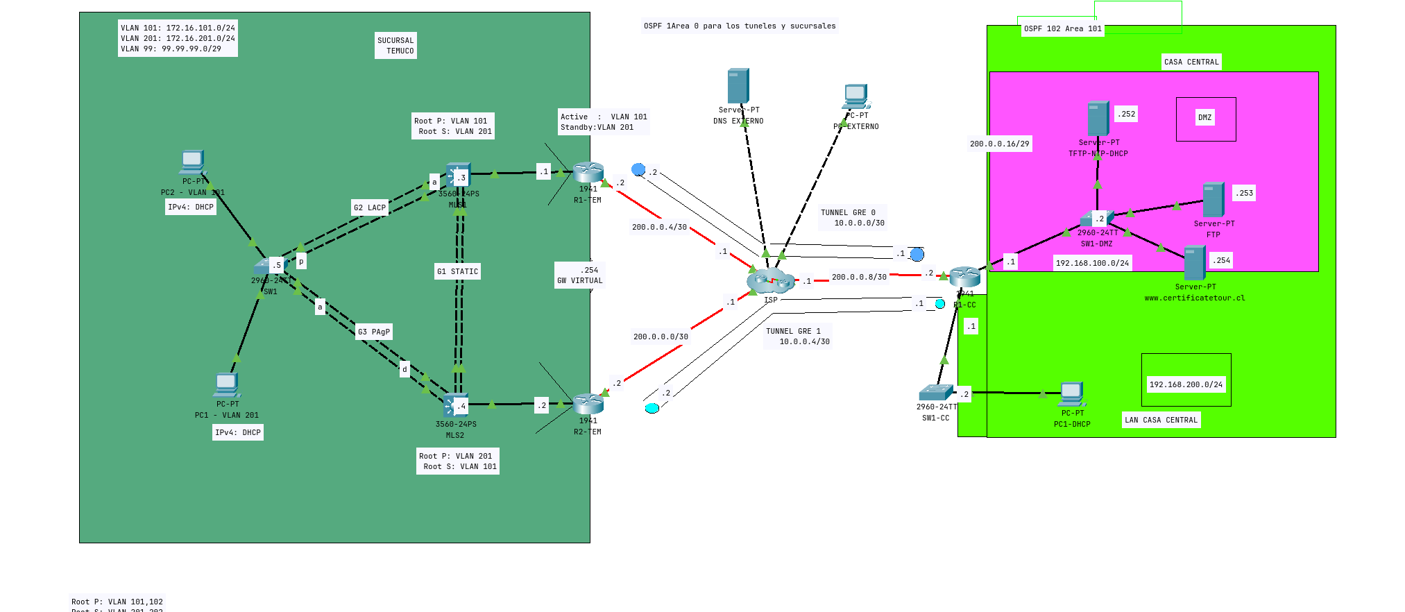
III.- CONFIGURACIONES SUCURSAL TEMUCO
Nota: Deje las configuraciones básicas para el final.
Deberán aplicar una configuración básica a cada equipo, nombre del dispositivo y contraseñas, considerando los controles de acceso a los equipos de red aplicando los parámetros necesarios.
Hostname según topología
Enable secret certour
Habilitar la línea de consola
Crear usuario con los siguientes parámetros: usuario: admin y contraseña cifrada: admin
Line vty login local
Banner motd SOLO USUARIOS AUTORIZADOS
Deberán asignar las direcciones IP según indicaciones de la topología, solo en IPv4.
Junto con los elementos mencionados en las configuraciones generales solicitadas, considere además las siguientes configuraciones específicas a realizar.
VLAN
Nombre
Direccion IPv4
Puertos
101
SALA_VENTAS
172.16.101.0/24
SW1 F0/1-10
201
COLABORADORES
172.16.201.0/24
SW1 F0/11-20
99
ADM/NATIVE
99.99.99.0/24
N/A
Cada SWITCH de TEMUCO deben tener su ip y gateway correspondiente según topología
Configurar seguridad de puerto en el switch “SW1 ”, para que el puerto conectado al PC acepte solo 1 MAC, y en caso de violación de seguridad, el puerto deberá colocarse en estado de Error-Disable. El switch debe aprender de forma dinámica las direcciones MAC.
Utilizar VLAN 99 para administración de todos los switches de la red, asignar direcciones propuestas en la topología.
Configurar en switch protocolo de agregación de enlaces.
Grupo
Tipo Enlace
Puertos
1
Static MLS1(on) - MLS2(on)
F0/19 - F0/20
2
LACP MLS1(a) - SW1(p)
F0/21 - F0/22
3
PAgP MLS2(d) - SW1(a)
F0/23 - F0/24
En SUCURSAL TEMUCO existen 2 PC que están asociados a diferentes VLAN, en IPv4 debe obtener dirección mediante DHCP que se debe configurar en Servidor DHCP de CASA CENTRAL
Nombre Pool
Start IP
Gateway
DNS
N° Max IP
VLAN 101
172.16.101.11
172.16.101.254
8.8.8.8
200
VLAN 201
172.16.201.11
172.16.201.254
8.8.8.8
200
DNS EXTERNO 8.8.8.8 ya está configurado para el dominio www.certificatetour.cl
Nube ISP ya está configurada
Configurar STP en los switch correspondientes, MLS1 debe ser Root Bridge primario para VLAN 101 y Root Bridge Secundario para VLAN 201 , MLS2 debe ser Root Bridge primario para VLAN 201 y Root Bridge Secundario para VLAN 101.
No olvide declarar troncales los puertos que lo requieran.
Evitar que puertos de acceso envíen o reciban BPDU
Habilitar configuración para que puertos de acceso pasen de estado deshabilitado a reenvió de forma inmediata.
V.- REQUERIMIENTOS DE PROTOCOLO DE REDUNDANCIA L3
Nota: El track es de la tabla VII, fusionarlas simplifica los pasos
Configurar de redundancia de capa de capa 3, a través de los Router R1-TEM y R2-TEM.
Dispositivo
Activo (105)
Standby (Default)
Virtual IP
Track
R1-TEM
VLAN 101,99
Vlan 201
.254
S0/0/0
R2-TEM
VLAN 201
VLAN 101,99
.254
S0/0/1
Realizar configuración apropiada para que, en caso de alguna caída de enlace principal, tome enlace de respaldo. Si el enlace vuelve a estar operativo debe tomar nuevamente su rol principal.
Modificar los timers para todas las VLAN ; 1seg el hello y 3seg el dead para tener una convergencia más rápida.
VI- REQUERIMIENTOS DE NAT TEMUCO
Configurar PAT en SUCURSAL TEMUCO, permitiendo la salida a internet para todas las VLAN
Descripcion
Nombre/Interfaz
ACL Estandard Nombrada (No incluya vlan 99)
WEB
Sobrecarga R1-TEM
S0/0/0
Sobrecarga R2-TEM
S0/0/0
VII.- REQUERIMIENTOS DE ENRUTAMIENTO
Considerar en enrutamiento Inter-vlan entre la VLAN 101, VLAN 201, y VLAN 99 con su configuración respectiva.
Configurar como protocolo de enrutamiento OSPFv2 entre TEMUCO y CASA CENTRAL por medio de los túneles, proceso 1 área 0.
En Temuco Declare en las subinterfaces el protocolo, en la interfaz tunnel declare con el comando network con wilcard de subred.
En Casa Central declare en las interfaces lan el protocolo , en las interfaces Tunnel declare el comando network con wilcard de subred
Utilizar como router-id:
R1-CC 1.1.1.1
R1-TEM 2.2.2.2
R2-TEM 3.3.3.3
Configurar rutas estáticas por defecto de Interfaz saliente para alcanzar al peer de CASA CENTRAL, pruebe conectividad de extremo a extremo en la red pública.
VIII.- REQUERIMIENTOS DE TUNNEL
Configurar tunnel GRE 0 en los router R1-TEM y R1-CC
Tunnel
Direccion IP
Modo
0
10.0.0.0/30
GRE
Configurar Tunnel GRE 1 en los router R2-TEM y R1-CC
Tunnel
Direccion IP
Modo
1
10.0.0.4/30
GRE
IX.- CONFIGURACIONES SUCURSAL CASA CENTRAL
Nota: Deje las configuraciones básicas para el final.
Deberán aplicar una configuración básica a cada equipo, nombre del dispositivo y contraseñas, considerando los controles de acceso a los equipos de red aplicando los parámetros necesarios.
Hostname según topología
Enable secret certour
Habilitar la línea de consola
Crear usuario con los siguientes parámetros: usuario: admin y contraseña cifrada: admin
Line vty login local
Banner motd SOLO USUARIOS AUTORIZADOS
Deberán asignar las direcciones IP según indicaciones de la topología, solo en IPv4.
X.- REQUERIMIENTOS DE SWITCH CASA CENTRAL
N/A
SW1-CC
SW1-DMZ
VLAN
1
1
IP
192.168.200.2/24
192.168.100.2/24
Gateway
192.168.200.1
192.168.100.1
XI.- REQUERIMIENTOS DHCP EN CASA CENTRAL
Crear un pool dhcp en Router R1-CC para que los hosts de LAN CASA CENTRAL obtengan el direccionamiento con la siguiente configuracion Servidor DHCP R1-CC
Nombre del Pool
Red
Gateway
DNS
Exclusion
LAN_CASA_CENTRAL
192.168.200.0/24
192.168.200.1
8.8.8.8
IP 1 a IP 10
XII- REQUERIMIENTOS DE NAT CASA CENTRAL
Configurar PAT Y nat estático en SUCURSAL CASA CENTRAL, permitiendo la salida a internet para LAN CASA CENTRAL.
En CASA CENTRAL la sobrecarga para LAN CASA CENTRAL es sobre el pool llamado INTERNET (una ip)
En CASA CENTRAL realizar un Nat estático para el servidor www.certificatetour.cl
Prefijo entregado por ISP
Nombre del Pool
ACL para PAT
IP para PAT
IP NAT estatico para www.certificatetour.cl
200.0.0.16/29
INTERNET
NAT-LAN
200.0.0.17
200.0.0.18
XIII- REQUERIMIENTOS DE SEGURIDAD
Configurar algún mecanismo de seguridad que evite que todos los servidores de DMZ accedan a LAN CASA CENTRAL.
La ACL es estándar numerada 10.
Habilitar lo más cerca del destino.
XIV- REQUERIMIENTOS DE SERVICIOS (Ejemplos en el PDF)
En CASA CENTRAL habilite el servicio TFTP para respaldar los archivos de configuración de inicio (startup-config) de los dispositivos intermediarios de TEMUCO.
En CASA CENTRAL habilite el servicio NTP para que los dispositivos intermediarios de TEMUCO sincronicen su reloj, la key “1” contraseña MD5 “ntp”
XV. RESULTADOS RQUERIDOS
Host de TEMUCO deben obtener ip desde servidor dhcp que esta en DMZ
Host de LAN CASA CENTRAL deben obtener ip desde R1-CC
Los Router de las sucursales deben tener vecindad mediante OSPF , se declaran las redes de cada sucursal y las redes de los tunnels
PC EXTERNO debe poder conectar a www.certificatetour.cl, DNS EXTERNO ya tiene el registro
Dispositivos Intermediarios de TEMUCO deben poder respaldar archivos de configuración de inicio en servidor TFTP en DMZ
Dispositivos Intermediarios de TEMUCO deben poder sincronizar sus relojes a través del servidor NTP en DMZ.
Si enlace entre R1-TEM e ISP se cae, R2-TEM debe ser activo para VLAN 101 , VLAN 99 y VLAN 201
Si enlace entre R2-TEM e ISP se cae, R1-TEM debe ser activo para VLAN 101 , VLAN 99 y VLAN 201
Configuracion
Dispositivos Finales
PC2 VLAN 101
IPv4: DCHP
DNS: 8.8.8.8
PC1 VLAN 201
IPv4: DHCP
DNS: 8.8.8.8
DNS Externo (Listo)
IPv4: 8.8.8.8
Mask: 255.255.255.0
DG: 8.8.8.1
DNS: 8.8.8.8
PC Externo (Listo)
IPv4: 200.10.10.10
Mask: 255.255.255.0
DG: 200.10.10.1
DNS: 8.8.8.8
Server TFTP NTP DHCP
Nota: Encender y configurar los servicios (Final, XV)
Nota: Falta Habilitar DNS y Agregar el Registro HTTP
IPv4: 192.168.100.252
Mask: 255.255.255.0
DG: 192.168.100.1
DNS: 192.168.100.252
SERVER FTP
IPv4: 192.168.100.253
Mask: 255.255.255.0
DG: 192.168.100.1
DNS: 192.168.100.252
SERVER HTTP
IPv4: 192.168.100.254
Mask: 255.255.255.0
DG: 192.168.100.1
DNS: 192.168.100.252
PC1-DHCP
IPv4: DHCP
Mask: DHCP
DG: DHCP
DNS: 8.8.8.8
SW1
!
enable
config t
!
hostname SW1
!
vlan 101
name SALA_VENTAS
exit
!
vlan 201
name COLABORADORES
exit
!
vlan 99
name ADM/NATIVE
exit
!
int range f0/1-f0/10
switchport mode access
switchport access vlan 101
switchport port-security
switchport port-security maximum 1
switchport port-security mac-address sticky
switchport port-security violation shutdown
spanning-tree portfast
spanning-tree bpduguard enable
switchport nonegotiate
no shut
exit
!
int range f0/11-f0/20
switchport mode access
switchport access vlan 201
switchport port-security
switchport port-security maximum 1
switchport port-security mac-address sticky
switchport port-security violation shutdown
spanning-tree portfast
spanning-tree bpduguard enable
switchport nonegotiate
no shut
exit
!
int range f0/21,f0/22
channel-group 2 mode passive
!
int port-channel 2
swithcport mode trunk
switchport trunk allowed vlan 101,201
switchport trunk native vlan 99
switchport nonegotiate
no shut
exit
!
int range f0/23,f0/24
channel-group 3 mode auto
exit
!
int port-channel 3
switchport mode trunk
switchport trunk allowed vlan 101,201
switchport trunk native vlan 99
switchport nonegotiate
no shut
exit
MLS1
!
enable
config t
!
hostname MLS1
!
vlan 101
name SALA_VENTAS
exit
!
vlan 201
name COLABORADORES
exit
!
vlan 99
name ADM/NATIVE
exit
!
int range f0/19,f0/20
channel-group 1 mode on
exit
!
int port-channel 1
switchport mode trunk
switchport trunk allowed vlan 101,201
switchport trunk native vlan 99
switchport nonegotiate
no shut
exit
!
int range f0/21,f0/22
channel-group 2 mode active
!
int port-channel 2
swithcport mode trunk
switchport trunk allowed vlan 101,201
switchport trunk native vlan 99
switchport nonegotiate
no shut
exit
!
spanning-tree vlan 101 root primary
spanning-tree vlan 201 root secondary
!
MLS2
!
enable
config t
!
hostname MLS2
!
vlan 101
name SALA_VENTAS
exit
!
vlan 201
name COLABORADORES
exit
!
vlan 99
name ADM/NATIVE
exit
!
int range f0/19,f0/20
channel-group 1 mode on
exit
!
int port-channel 1
switchport mode trunk
switchport trunk allowed vlan 101,201
switchport trunk native vlan 99
switchport nonegotiate
no shut
exit
!
int range f0/23,f0/24
channel-group 3 mode desirable
exit
!
int port-channel 3
switchport mode trunk
switchport trunk allowed vlan 101,201
switchport trunk native vlan 99
switchport nonegotiate
no shut
exit
!
spanning-tree vlan 201 root primary
spanning-tree vlan 101 root secondary
!
SW1-CC
!
enable
config t
!
hostname SW1-CC
!
enable secret certour
!
line console 0
username admin pass admin
service password-encryption
exit
!
line vty 0 4
pass certour
login
exit
!
banner motd # SOLO USUARIOS AUTORIZADOS#
!
vlan 1
exit
!
SW1-DMZ
!
enable
config t
!
hostname SW1-DMZ
!
enable secret certour
!
line console 0
username admin pass admin
service password-encryption
exit
!
line vty 0 4
pass certour
login
exit
!
banner motd # SOLO USUARIOS AUTORIZADOS#
!
vlan 1
exit
!
R1-TEM
!
enable
config t
!
int S0/0/0
ip add 200.0.0.6 255.255.255.252
no shut
exit
!
int g0/1
no shut
exit
!
int g0/1.101
encapsulation dot1q 101
ip add 171.16.101.1 255.255.255.0
standby version 2
standby X ip 172.16.101.254
standby X priority 105
standby X preempt
standby X timers 1 3
standby X track Serial 0/0/0
no shut
exit
!
int g0/1.99
encapsulation dot1q 101
ip add 99.99.99.1 255.255.255.248
standby version 2
standby X ip 99.99.99.254
standby X priority 105
standby X preempt
standby X timers 1 3
standby X track Serial 0/0/0
no shut
exit
!
g0/1.201
encapsulation dot1q 201
ip add 172.16.201.1 255.255.255.0
standby version 2
standby X ip 172.16.201.254
standby X priority 100
standby X timers 1 3
standby X track Serial 0/0/0
no shut
exit
!
ip route 0.0.0.0 0.0.0.0 200.0.0.5
!
int tunnel 0
ip address 10.0.0.2 255.255.255.252
tunnel source s0/0/0
tunnel destination 10.0.0.1
tunel mode gre ip
R2-TEM
!
enable
config t
!
int S0/0/1
ip add 200.0.0.2 255.255.255.252
no shut
exit
!
int g0/1
no shut
exit
!
int g0/1.201
encapsulation dot1q 201
ip add 172.16.201.2 255.255.255.0
standby version 2
standby X ip 172.16.201.254
standby X priority 105
standby X preempt
standby X timers 1 3
standby X track Serial 0/0/1
no shut
exit
!
int g0/1.101
encapsulation dot1q 101
ip add 172.16.101.2 255.255.255.0
standby version 2
standby X ip 172.16.101.254
standby X priority 100
standby X timers 1 3
standby X track Serial 0/0/1
no shut
exit
!
int g0/1.99
encapsulation dot1q 99
ip add 99.99.99.2 255.255.255.248
standby version 2
standby X ip 99.99.99.254
standby X priority 100
standby X timers 1 3
standby X track Serial 0/0/1
no shut
exit
!
int tunnel 1
ip add 10.0.0.6 255.255.255.252
tunnel source s0/0/1
tunnel destination 10.0.0.5
tunnel mode gre ip
!
ip route 0.0.0.0 0.0.0.0 200.0.0.1
!
R1-CC
!
enable
config t
!
int s0/1/0
ip add 200.0.0.10 255.255.255.252
no shut
exit
!
int tunnel 0
ip address 10.0.0.1 255.255.255.252
tunnel source s0/1/0
tunnel destination 10.0.0.2
tunnel mode gre ip
!
int tunnel 1
ip add 10.0.0.5 255.255.255.252
tunnel source s0/1/0
tunnel destination 10.0.0.6
tunnel mode gre ip
!
ip route 0.0.0.0 0.0.0.0 200.0.0.9
!
ip dhcp excluded-address 192.168.200.1 192.168.200.10
ip dhcp pool LAN_CASA_CENTRAL
network 192.168.200.1 255.255.255.0
default-router 192.168.200.1
dns-server 8.8.8.8
exit
!